当前数字电路系统的设计正朝着速度快、容量大、体积小、重量轻的方向发展。利用大规模可编程逻辑器件CPLD(Complex Programmable Logic Device)进行ASIC设计,可以直接面向用户需求,根据对系统的功能要求自上而下地逐层完成相应的描述、综合、优化、仿真与验证,直到生成元器件。目前,系统级的仿真工具也已出现.这样可以大大地缩短系统的设计周期,增加可靠性,提高产品竞争能力。采用Altera和Xilinx公司的可编程逻辑器件,并配以开发软件可在计算机上进行各种电路设计和修改,并可对电路特性进行仿真模拟,最后将设方案下载到该器件中,这样可实现高度集成和精确的电路设计,降低了设计成本,提高了设计效率和电路的可靠性。本文通过一个汽车车灯控制系统的设计实践,介绍了VHDL语言的具体设计应用。
1 系统功能及要求
汽车上有一转弯控制杆,此杆有三种状态:中间位置时汽车不转弯,向上位置时汽车左转,向下位置时汽车右转。汽车转弯时相应的尾灯和头灯均闪烁,当应急开关合上时,头灯尾灯均闪烁。汽车刹车时,2个尾灯发出一直亮的信号。如果汽车刹车时正在转弯,则相应的转弯闪烁信号不受影响。
2 逻缉抽象
由要求转换成真值表
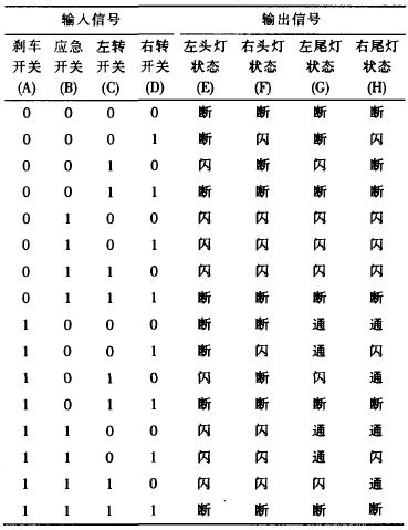
注:断-灯不亮;闪-灯闪烁;通-灯一直亮
3 由真值表得出逻辑表达式
E(断)=(C and D)or((not B)and(not C));
E(闪)=(B and(not C))Or(C and(not D));
E(通)=0;
F(断)=(C and D)OR((not B)and(not D));
F(闪)=((not C)and D)Or(B and(not D));
F(通)=0;
G(断)=(C and D)or((not A)and(not B)and(not C));
G(闪)=(C and(not D))or((not A)and B and(not C));
G(通)=A and(not C);
H(断)=(C and D)or((not A)and(not B)and(not D));
H(闪)= not C)and D)or((not A)and B and(not D));
H(通)=A and(not D);
4 VHDL语言实现(源程序注释)
代码
- library IEEE --定义IEEE库,使用std_logic_1164和std_logic_unsigned
- use IEEE.std_logic_1164.all; --包集合
- use IEEE.std_logic_unsigned.all;
- entity autolight is --定义实体autolight
- port(A.in STD_LOGIC;
- C:in STD_LOGIC;
- B:in STD_LOGIC;
- D:in STD_LOGIC;
- E:out STD_LOGIC;
- F:out STD_LOGIC;
- G:out STD_LOGIC;
- H:out STD_ LOGIC);
- --说明:定义器件的输入输出口字母用大写。A、B、C、D对应上述四个开关,信号为输入;E、F、G、H对应上述前后车灯,信号为输出。
- end autolight;
- architecture autolight_arch of autolight is --构造体说明
- signal e1,e2,e3,f1,f2,f3,g1,g2,g3,h1,h2,h3,clkk,
- sel:std_logc;
- signal controle,controlf,controlg,controlh:std_logic_vector(2 downto 0);
- --说明:定义器件内部信号口的字母用小写。e1对应E(断),e2对应E(闪),e3对应E(通)。f1、f2、t3、g1、g2、g3、h1、h2、h3同理。
- component clk --元件clk以产生闪烁信号
- port(clkin:in std_logic;clkout:out std_logic); --脉冲(为方波)
- end component;
- component os --元件os相当于晶体振荡器
- port(osout:out std-logic); --产生约8mhz脉冲
- end component;
- begin
- u1:os port map(clkk); --调用os产生信号clkk
- u2:clk port map(clkk,se1); --调用clk产生信号,sel用于闪烁
- --light e -产生e1,e2,e3,f1,f2,f3,gl,g2,g3
- e1<=((not b)and(not c))or(c and d);hl,h2,h3信号
- e2<=(b and(not c))or(c and(not d));一如e1=1则左头灯不亮
- e3<='0'; --如e2=1则左头灯闪烁,如e3=1则左头灯一直亮
- --light f -同一时刻e1、e2、e3只会有一个为1
- f1<=((not b)and(not d))or(c and d);
- f2<=((not c)and d)or(b and(not d));
- f3<='0';
- --light g
- g1<=((not a)and(not b)and(not c))or(c and d);
- g2<=((not a)and b and(not c))or(c and(not d));
- g3<=a and(not c);
- --light h
- h1<=((not a)and(not b)and(not d))or(c and d);
- h2<=((not C)and d)or((not a)and b and(not d));
- h3<=a and(not d);
- --control signal--controle controlf controlg controlh
- controle<=e1&e2&e3;--为位矢量(2 downto 0),该位变量值
- controlf<=f1&f2&f3;--等于e1、e2、e3组合,只可能为100、010
- controlg<=g1&g2&g3;001之一
- controlh<=h1&h2&h3;
- --light signal of flash is clkin2
- e<='0' when controle="O01" else --on
- 如controle=100则左头灯不亮
- sel when controle="010" else --flash
- 如controle=010则左头灯闪烁
- '1': --off
- 如controle=O01则左头灯一直亮
- f<='0' when controlf="001" else --on
- sel when controlf="010" else --flash
- '1';--off
- g<='0' when controlg="001" else --on
- sel when controlg="010" else --flash
- '1' ;--off
- h<='0' when controlh="001" else --on
- sel when controlh="010" else --flash
- '1' ;--off
- end autolight_arch;--结束构造体autolight_arch
5 管脚锁定文件说明
用户可根据使用情况自行定义管脚锁定文件。这里将用EDA实验板上资源(跳线,开关按键,数码管,LED指示灯,蜂鸣器等)与xilinx xc9572芯片管脚相连,使用者可通过对按键和开关的操作加上指示灯和数码管的显示来判断程序是否正确。本系统使用xc9572中p33、p34、p35、p36作为输人端,对应程序中A、B、C、D,在EDA实验板上对应跳线的最左边四个。使用p29、p28作为左右头灯,对应LED发光管最左边两个。使用p40、p42作为左右尾灯,对应LED发光管最右边两个。
6 元件clk说明
代码
- library IEEE;
- use IEEE.std_logic_1164.all;
- use IEEE.std_logic_unsigned.all;
- entity clk is_clk的作用是分频以产生闪烁信号
- port(
- clkin:in std_logic;
- clkout:out STD_LOGIC);
- end clk;
- architecture clk_arch of clk is
- signal clk:STD_LOGIC;
- signal counter:std_logic_vector(24 downto 0);
- begin
- clkout<=counter(24);
- process(CLKin)
- begin
- if CLKin= '1' and CLKin'event then
- COUNTER<=COUNTER+1;
- end if;
- end process;
- end clk_arch;
-
 热敏电阻温度阻值查询程序2024年11月13日 74
 -
C99语法规则2024年11月16日 675
-
 FreeRTOS 动态内存管理2024年11月12日 448
 -
一款常用buffer程序2024年11月06日 88
-
 1602液晶显示模块的应用2012年08月03日 192
 -
GNU C 9条扩展语法2024年11月18日 261
-
 如何实现STM32F407单片机的ADC转换2024年11月15日 300
 -
 STM32使用中断屏蔽寄存器BASEPRI保护临界段2024年11月15日 195
-
C99语法规则2024年11月16日 675
-
 51单片机LED16*16点阵滚动显示2012年09月05日 664
 -
FreeRTOS 动态内存管理2024年11月12日 448
-
 ARM9远程图像无线监控系统2012年07月03日 424
 -
 用单片机模拟2272软件解码2012年09月06日 300
 -
如何实现STM32F407单片机的ADC转换2024年11月15日 300
-
 新颖的单片机LED钟2012年08月06日 278
 -
GNU C 9条扩展语法2024年11月18日 261