----------------------------------------------------------------
--
-- Copyright (c) 1992,1993,1994, Exemplar Logic Inc. All rights reserved.
--
----------------------------------------------------------------
--
-- This design implements a UART.
--
--
--Version 1.1 : Original Creation
--Version 1.2 : Modified to std_logic types
--Version 2.1 : Extended reset to be more effective.
--Introduced OTHERS clause.
------------------------------------------------------------------
LIBRARY ieee;
use ieee.std_logic_1164.all;
use ieee.std_logic_arith.all;
use ieee.std_logic_unsigned.all;
ENTITY uart IS
PORT (clkx16 : INstd_logic; -- Input clock. 16x bit clock
read : INstd_logic; -- Received data read strobe
write : INstd_logic; -- Transmit data write strobe
rx : INstd_logic; -- Receivedata line
reset : INstd_logic; -- clear dependencies
tx : OUTstd_logic; -- Transmit data line
rxrdy : OUTstd_logic; -- Received data ready to be read
txrdy : OUTstd_logic; -- Transmitter ready for next byte
parityerr : OUTstd_logic; -- Receiver parity error
framingerr : OUTstd_logic; -- Receiver framing error
overrun : OUTstd_logic; -- Receiver overrun error
data : INOUT std_logic_vector(0 TO 7)); -- Bidirectional data bus
END uart;
ARCHITECTURE exemplar OF uart IS
-- Transmit data holding register
SIGNALtxhold : std_logic_vector(0 TO 7);
-- Transmit shift register bits
SIGNALtxreg : std_logic_vector(0 TO 7);
SIGNALtxtag2 : std_logic; -- tag bits for detecting
SIGNALtxtag1 : std_logic; --empty shift reg
SIGNALtxparity : std_logic; -- Parity generation register
-- Transmit clock and control signals
SIGNALtxclk : std_logic;-- Transmit clock: 1/16th of clkx16
SIGNALtxdone : std_logic; -- '1' when shifting of byte is done
SIGNAL paritycycle : std_logic; -- '1' on next to last shift cycle
SIGNALtxdatardy : std_logic;-- '1' when data is ready in txhold
-- Receive shift register bits
SIGNALrxhold : std_logic_vector(0 TO 7);-- Holds received data for read
SIGNALrxreg : std_logic_vector(0 TO 7);-- Receive data shift register
SIGNALrxparity : std_logic; -- Parity bit of received data
SIGNALparitygen : std_logic; -- Generated parity of received data
SIGNALrxstop : std_logic; -- Stop bit of received data
-- Receive clock and control signals
SIGNALrxclk : std_logic; -- Receive data shift clock
SIGNALrxidle : std_logic;-- '1' when receiver is idling
SIGNALrxdatardy : std_logic;-- '1' when data is ready to be read
BEGIN
make_txclk:
PROCESS (reset, clkx16)
VARIABLE cnt: std_logic_vector(2 DOWNTO 0);
BEGIN
-- Toggle txclk every 8 counts, which divides the clock by 16
IF reset='1' THEN
txclk <= '0' ;
cnt := (OTHERS=>'0') ;
ELSIF clkx16'event AND clkx16='1' THEN
IF (cnt = "000") THEN
txclk <= NOT txclk;
END IF;
cnt := cnt + "001"; -- Use the exemplar_1164 "+" on std_logic_vector
END IF;
END PROCESS;
make_rxclk:
PROCESS(reset, clkx16)
VARIABLE rxcnt : std_logic_vector(0 TO 3); -- Count of clock cycles
VARIABLE rx1: std_logic; -- rx delayed one cycle
VARIABLE hunt: boolean; -- Hunting for start bit
BEGIN
IF reset='1' THEN
-- Reset all generated signals and variables
hunt := FALSE ;
rxcnt := (OTHERS=>'0') ;
rx1 := '0' ;
rxclk <= '0' ;
ELSIF clkx16'EVENT AND clkx16 = '1' THEN
-- rxclk = clkx16 divided by 16
rxclk <= rxcnt(0);
-- Hunt=TRUE when we are looking for a start bit:
--A start bit is eight clock times with rx=0 after a falling edge
IF (rxidle = '1' AND rx = '0' AND rx1 = '1') THEN
-- Start hunting when idle and falling edge is found
hunt := TRUE;
END IF ;
IF rxidle = '0' OR rx = '1' THEN
-- Stop hunting when shifting in data or a 1 is found on rx
hunt := FALSE;
END IF;
rx1 := rx; -- rx delayed by one clock for edge detection
-- (Must be assigned AFTER reference)
-- Increment count when not idling or when hunting
IF (rxidle = '0' OR hunt) THEN
-- Count clocks when not rxidle or hunting for start bit
rxcnt := rxcnt + "0001";
ELSE
-- hold at 1 when rxidle and waiting for falling edge
rxcnt := "0001";
END IF;
END IF ;
END PROCESS;
-- transmit shift register:
txshift:
PROCESS (reset, txclk)
BEGIN
IF reset='1' THEN
txreg <= (OTHERS=>'0') ;
txtag1 <= '0' ;
txtag2 <= '0' ;
txparity <= '0' ;
tx <= '0' ;
ELSIF txclk'event AND txclk = '1' THEN
IF (txdone AND txdatardy) = '1'THEN
-- Initialize registers and load next byte of data
txreg<= txhold; -- Load tx register from txhold
txtag2<= '1';-- Tag bits for detecting
txtag1<= '1';--when shifting is done
txparity <= '1';-- Parity bit.Initializing to 1==odd parity
tx<= '0';-- Start bit
ELSE
-- Shift data
txreg <= txreg(1 TO 7) & txtag1;
txtag1<= txtag2;
txtag2<= '0';
-- Form parity as each bit goes by
txparity<= txparity XOR txreg(0);
-- Shift out data or parity bit or stop/idle bit
IF txdone = '1' THEN
tx <= '1'; -- stop/idle bit
ELSIF paritycycle = '1' THEN
tx <= txparity; -- Parity bit
ELSE
tx <= txreg(0); --Shift data bit
END IF;
END IF ;
END IF;
END PROCESS;
-- paritycycle = 1 on next to last cycle (When txtag2 has reached txreg(1))
--(Enables putting the parity bit out on tx)
paritycycle <= txreg(1) AND NOT (txtag2 OR txtag1 OR
txreg(7) OR txreg(6) OR txreg(5) OR
txreg(4) OR txreg(3) OR txreg(2));
-- txdone = 1 when done shifting (When txtag2 has reached tx)
txdone <= NOT (txtag2 OR txtag1 OR
txreg(7) OR txreg(6) OR txreg(5) OR txreg(4) OR
txreg(3) OR txreg(2) OR txreg(1) OR txreg(0));
rx_proc:-- Shift data on each rxclk when not idling
PROCESS (reset, rxclk)
BEGIN
IF reset='1' THEN
rxreg <= (OTHERS=>'0') ;
rxparity <= '0' ;
paritygen <= '0' ;
rxstop <= '0' ;
ELSIF rxclk'event AND rxclk = '1' THEN
IF rxidle = '1' THEN
-- Load all ones when idling
rxreg <= (OTHERS=>'1');
rxparity <= '1';
paritygen <= '1'; -- Odd parity
rxstop <= '0';
ELSE
-- Shift data when not idling
-- bug in assigning to slices
-- rxreg (0 TO 6) <= rxreg (1 TO 7);
-- rxreg(7) <= rxparity;
rxreg <= rxreg (1 TO 7) & rxparity;
rxparity <= rxstop;
paritygen <= paritygen XOR rxstop;-- Form parity as data shifts by
rxstop <= rx;
END IF ;
END IF;
END PROCESS;
async:-- rxidle requires async preset since it is clocked by rxclk and
-- its value determines whether rxclk gets generated
PROCESS ( reset, rxclk )
BEGIN
IF reset = '1' THEN
rxidle <= '0';
ELSIF rxclk'EVENT and rxclk = '1' THEN
rxidle <= NOT rxidle AND NOT rxreg(0);
END IF;
END PROCESS async;
txio: -- Load txhold and set txdatardy on falling edge of write
-- Clear txdatardy on falling edge of txdone
PROCESS (reset, clkx16)
VARIABLE wr1,wr2: std_logic; -- write signal delayed 1 and 2 cycles
VARIABLE txdone1: std_logic;-- txdone signal delayed one cycle
BEGIN
IF reset='1' THEN
txdatardy <= '0' ;
wr1 := '0' ;
wr2 := '0' ;
txdone1 := '0' ;
ELSIF clkx16'event AND clkx16 = '1' THEN
IF wr1 = '0' AND wr2= '1' THEN
-- Falling edge on write signal. New data in txhold latches
txdatardy<= '1';
ELSIF txdone = '0' AND txdone1 = '1' THEN
-- Falling edge on txdone signal. Txhold has been read.
txdatardy<= '0';
END IF;
-- Delayed versions of write and txdone signals for edge detection
wr2 := wr1;
wr1 := write;
txdone1 := txdone;
END IF ;
END PROCESS;
rxio:
PROCESS (reset, clkx16)
VARIABLE rd1, rd2 : std_logic; -- Read input delayed 1 and 2 cycles
VARIABLE rxidle1: std_logic; -- rxidle signal delayed 1 cycle
BEGIN
IF reset='1' THEN
overrun <= '0' ;
rxhold <= (OTHERS=>'0') ;
parityerr <= '0' ;
framingerr <= '0' ;
rxdatardy <= '0' ;
rd1 := '0' ;
rd2 := '0' ;
rxidle1 := '0' ;
ELSIF clkx16'event AND clkx16 = '1' THEN
-- Look for rising edge on idle and update output registers
IF rxidle = '1' AND rxidle1 = '0' THEN
IF rxdatardy = '1' THEN
-- Overrun error if previous data is still there
overrun <= '1';
ELSE
-- No overrun error since holding register is empty
overrun <= '0';
-- Update holding register
rxhold <= rxreg;
-- paritygen = 1 if parity error
parityerr <= paritygen;
-- Framingerror if stop bit is not 1
framingerr <= NOT rxstop;
-- Signal that data is ready for reading
rxdatardy <= '1';
END IF;
END IF;
rxidle1 := rxidle; -- rxidle delayed 1 cycle for edge detect
--Clear error and data registers when data is read
IF (NOT rd2 AND rd1) = '1' THEN
rxdatardy<= '0';
parityerr<= '0';
framingerr <= '0';
overrun<= '0';
END IF;
rd2 := rd1; -- Edge detect for read
rd1 := read; -- (Must be assigned AFTER reference)
IF reset = '1' THEN
rxdatardy <= '0';
END IF;
END IF ;
END PROCESS;
-- Drive data bus only during read
data <= rxhold WHEN read = '1' ELSE (OTHERS=>'Z') ;
-- Latch data bus during write
txhold <= data WHEN write = '1' ELSE txhold;
-- Receive data ready output signal
rxrdy <= rxdatardy;
-- Transmitter ready for write when no data is in txhold
txrdy <= NOT txdatardy;
-- Run-time simulation check for transmit overrun
ASSERT write = '0' OR txdatardy = '0'
REPORT "Transmitter overrun error" SEVERITY WARNING;
END exemplar;
-
 热敏电阻温度阻值查询程序2024年11月13日 74
 -
C99语法规则2024年11月16日 675
-
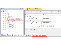 FreeRTOS 动态内存管理2024年11月12日 448
 -
一款常用buffer程序2024年11月06日 88
-
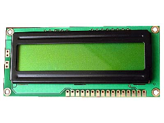 1602液晶显示模块的应用2012年08月03日 192
 -
GNU C 9条扩展语法2024年11月18日 261
-
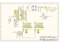
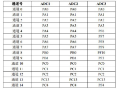 如何实现STM32F407单片机的ADC转换2024年11月15日 300
 -
 STM32使用中断屏蔽寄存器BASEPRI保护临界段2024年11月15日 195
-
C99语法规则2024年11月16日 675
-
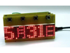
 51单片机LED16*16点阵滚动显示2012年09月05日 664
 -
FreeRTOS 动态内存管理2024年11月12日 448
-
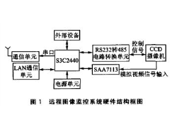 ARM9远程图像无线监控系统2012年07月03日 424
 -
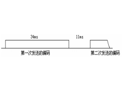 用单片机模拟2272软件解码2012年09月06日 300
 -
如何实现STM32F407单片机的ADC转换2024年11月15日 300
-
 新颖的单片机LED钟2012年08月06日 278
 -
GNU C 9条扩展语法2024年11月18日 261